
Scanning Edentulous Arches: Why Scans Fail and How to Prevent It
We took one real edentulous scan that arrived at our lab, measured every defect in it, and compared it with the version we had to rebuild. Here is what went wrong, why intraoral scanners struggle without teeth, and the published evidence on how to control it.
A real case, measured
The scan below is a mandibular edentulous arch exported from an iTero scanner and sent to us for a complete denture. Nothing about it is unusual. We receive scans like this every week, from many offices and on every scanner brand. We are using it because it shows every common failure in one file, and because we kept both the original export and the version our technician cleaned up for design. All patient and office identifiers have been removed.
We loaded both files into mesh-analysis software, aligned them in the same coordinate space, and measured what the cleanup had to remove and reshape.
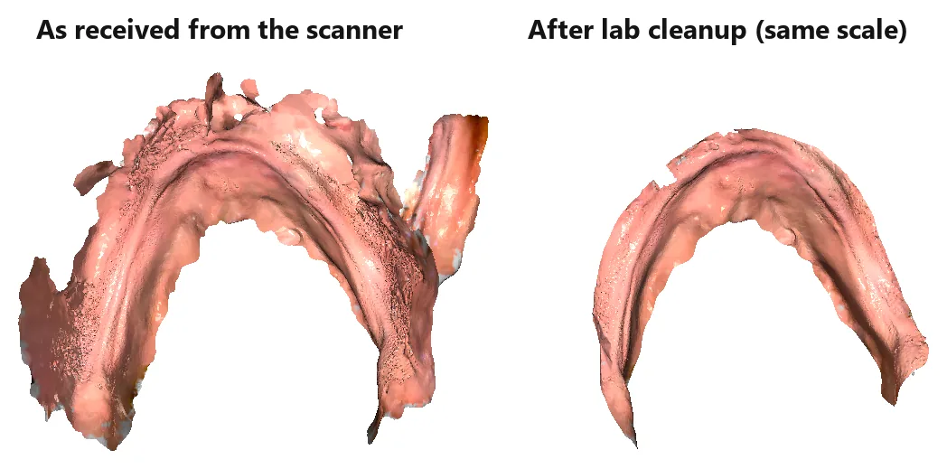
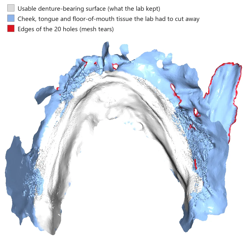
The first number is the important one. Two-thirds of what the scanner recorded was not denture-bearing tissue. It was cheek, tongue and floor of the mouth, captured while those tissues were moving. All 20 holes sat inside that discarded tissue, which shows how the tears formed: they appeared wherever soft tissue moved between frames.
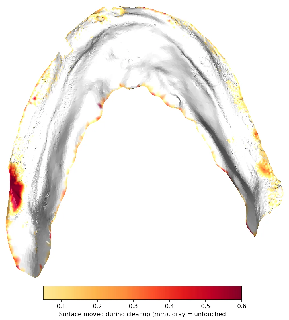
Trimming was not enough. Even inside the area we kept, 7.8% of the surface had to be moved by more than 0.1 mm and 2.3% by more than 0.3 mm (Figure 6, below). Every one of those corrections is a judgment call made by a technician who was not in the patient's mouth. The better the scan, the fewer of those guesses we have to make.
Why scanners struggle without teeth
An intraoral scanner does not take one picture of the arch. It captures thousands of small, overlapping 3D frames and stitches them together by matching the shape each new frame shares with the ones before it. Teeth are ideal for this: they are rigid, sharply contoured and do not move. An edentulous ridge offers almost none of that.
- Few landmarks to stitch on. A 2023 systematic review describes denture-bearing areas as "smooth, shiny, and devoid of clear anatomic landmarks," features it links to stitching errors.3 An earlier study put it as "large amounts of mobile tissue and the lack of obvious anatomic landmarks."5
- The surface moves. Mucosa, cheeks, lips and tongue shift between frames. The software assumes the surface is rigid, so when tissue moves it either records the same tissue twice in two positions or rejects the frames and leaves a gap.
- The errors land where dentures need accuracy most. In a clinical study of 29 edentulous patients, the largest deviations (≥ 500 µm) were in the soft palate, the sublingual areas and the vestibule (the peripheral seal zone). The authors concluded those scanners could not yet fully replace a conventional impression for a complete denture.4 The 2023 review reached the same pattern across 12 studies: peripheral borders, the inner seal and the soft palate show the largest discrepancies.3
- The mandible is harder. Two in vitro studies by the same group found better precision on the maxilla,78 and the 2023 review reports a larger mean deviation in the mandible than the maxilla in vivo.3 The tongue, floor of the mouth and narrow lingual tissue all get in the way.
- The scanner captures tissue at rest. A conventional final impression is border-molded: the tissues are moved through function while the material sets. A scan records whatever position the tissue was in at that moment, with no functional molding of the borders.
To be fair to the technology, scanners do perform well on the stable part of the ridge. In one clinical comparison of maxillary impressions, scans had overall deviations similar to PVS impressions.2 When peripheral areas were trimmed off both datasets, another clinical study found the difference between scans and conventional impressions fell to −0.02 ± 0.05 mm, which is within the range of mucosal resilience.9 The ridge itself is not the problem. The problems are the borders and everything the wand picks up around them.
Scanner choice matters too. The first in vitro test of four scanners on edentulous models found trueness ranging from 44 µm to 592 µm, and the authors could not recommend those four devices for edentulous jaws in vivo.1 Scanners have improved a great deal since 2013. For a current comparison of hardware, see our intraoral scanner comparison.
Each defect and what causes it
The "bubbly" or crazed surface
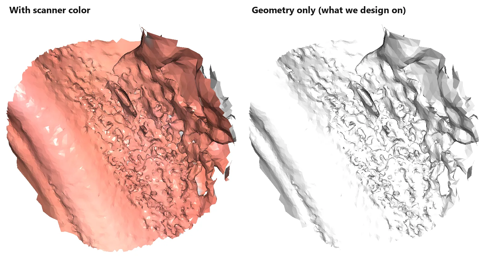
This is the defect doctors notice least and labs spend the most time on. Up close, large areas of the slopes look like bubble wrap or worm tracks (Figure 3). In color it can pass for normal tissue texture. With color turned off, which is the geometry we actually design on, you can see that it is not anatomy.
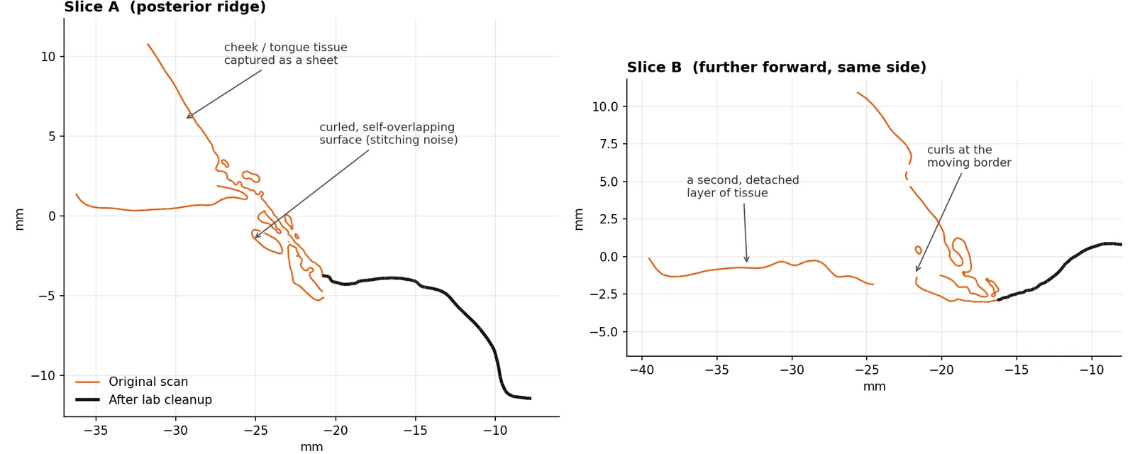
A cross-section explains it (Figure 4). We sliced both meshes through the same plane. Where the cleaned scan (black) is a single smooth line, the original (orange) splits into small closed loops and curls. These are many thin, overlapping copies of the surface, each recorded with the tissue in a slightly different position, that the software could not merge into one layer. Pooled saliva and bubbles in it can add to the effect. The literature on moisture alone is mixed, though: a 2026 review treated it as a likely confounder rather than a proven independent factor.11
Double layers and tissue "sheets"
When the wand sweeps past the cheek or tongue, the scanner records them as surface. If that tissue moves and the wand passes again, the scanner records it again in a new position. The result is a flap or a second sheet of tissue floating beside the ridge (Figure 4, slice B). The lab has to decide which layer is real. In this case it was obvious. Near the borders it often is not.
Tears and holes
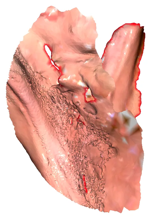
Holes form where the scanner rejected frames because the surface no longer matched what it had already recorded, usually because the tissue moved. In this scan every hole was in moving tissue, at the edge of a flap or in the floor of the mouth (Figure 5). A common reaction is to go back and "paint in" the hole. When the tissue has moved, that adds another overlapping layer instead of closing the gap.
Reshaped borders
After trimming and repairs, this is how far the technician had to move the surface that was kept. Most of the ridge is untouched (gray). The corrections, up to about 1 mm, run along the border, where the trim line crossed the noisy zone. That border is the denture's seal.
A protocol that controls it
No technique turns mobile mucosa into enamel. But most of the damage in this case came from things that can be controlled: what was in the field of view, how many passes were made, and how dry the tissue was.
1. Decide what the scan is for
If the scan is meant to replace the final impression, read the evidence above carefully. A well-supported hybrid is to scan the edentulous arch, have the lab design and print a custom tray from it, then make a conventional border-molded final impression in that tray. Lo Russo and colleagues used exactly this workflow in their clinical study.9 You keep the speed of the scan and still get a functional border. If the patient has an existing denture that fits reasonably well, scan that too. The export in this case included denture scans, and they help us cross-check the borders.
2. Control the field before the wand goes in
- Dry the tissue. Wipe pooled saliva with gauze and use light air before each segment, especially on the lingual side and in the floor of the mouth. Wet, glossy mucosa is harder for any optical system to read.
- Get the tongue and cheeks out of the field. Have an assistant hold the tongue and cheek with mirrors or a retractor, and keep holding during the scan. Retracting the lips, cheeks and tongue during edentulous scanning is recommended in the literature.3 Most of the 66% we trimmed in this case would not have been captured if it had never been in view.
- Avoid stretching tissue. Pulling hard on the cheek drags the vestibule into a position it never holds in function. Retract enough to clear the field, not enough to blanch the tissue.
3. Give the scanner something to stitch on
Adding artificial landmarks to a featureless ridge has measurable benefits in the lab. A small (4 × 3 mm) alumina landmark on a 26 mm edentulous span improved both trueness and precision for all three scanners tested.5 On edentulous typodonts, scanning spray, a liquid scanning aid, pressure-indicating paste lines and small composite markers all changed trueness, but the best option depended on the scanner.8 A 2025 pilot study on one patient, using iTero Element 5D and TRIOS 5, reported better accuracy and shorter scan times with 1 mm reference points placed every 5 mm.10 That is promising but very early evidence. Whatever you use, it has to be thin, stay still, and come off cleanly.
4. Scan in a planned, continuous path
- Follow a defined sequence. In an in vitro comparison of six strategies, the strategy significantly affected accuracy. A posterior-start path that runs along the lingual or palatal slope, comes back over the crest, and finishes on the buccal side performed best. A zig-zag path performed worst.7 The same group used that path in their follow-up work.8
- Splitting the mandible is fine. Several manufacturers recommend scanning one side of the mandible and then the other. In a clinical study of 20 mandibles, that two-step method showed no significant distortion compared with conventional impressions.6
- Capture the vestibule in one pass. The 2023 review recommends scanning the whole vestibule in a single pass, because going back over missed areas can introduce error.3
- Do not patch moving tissue. If a region is full of flaps or noise, erase it on the scanner and rescan that region once, cleanly. Repeated passes over tissue that has moved are what produced the layers in Figure 4.
- Include what we need, and only that. Retromolar pads, buccal shelves, the lingual slope down to the functional floor of the mouth, and the labial vestibule. You do not need the cheek, the tongue or the floor of the mouth.
One more point from the evidence: a 2026 review found scan quality most consistently linked to the scanner model and the scan strategy. Operator experience appeared to matter less with modern devices.11 A planned sequence your whole team follows is the part you control.
Before you press send
Spin the model on the scanner screen for 30 seconds before you submit it. If you see any of these, rescan that region while the patient is still in the chair:
| What you see | Likely cause | What to do now |
|---|---|---|
| Bubbly, pitted or worm-track texture on the slopes | Overlapping passes over tissue that moved, often with saliva present | Erase the region, dry it, retract, and rescan it in one slow pass |
| A flap or second "skin" beside the ridge | Cheek or tongue captured in two positions | Erase it, have the assistant hold retraction steady, and rescan |
| Holes on the crest, retromolar pad or buccal shelf | Frames rejected because the tissue moved or was wet | Dry the area and rescan it continuously from stable ridge into the gap |
| Holes only in the cheek, tongue or floor of the mouth | Tissue that should not have been captured | Trim it or leave it; the lab will remove it |
| Retromolar pads or vestibule missing | Not reached or blocked by soft tissue | Retract and scan those areas specifically |
Then upload the scan to us with the denture scans and bite records. For what we need on removable cases, see our complete dentures and implant overdentures pages.
Frequently asked questions
Can an intraoral scan replace a border-molded final impression for a complete denture?
Is the mandible or the maxilla harder to scan when edentulous?
Do scanning aids or landmarks help on edentulous ridges?
References
- Patzelt SBM, Vonau S, Stampf S, Att W. Assessing the feasibility and accuracy of digitizing edentulous jaws. J Am Dent Assoc. 2013;144(8):914-920. doi:10.14219/jada.archive.2013.0209 · PubMed 23904578peer-reviewed, in vitro
- Chebib N, Kalberer N, Srinivasan M, Maniewicz S, Perneger T, Müller F. Edentulous jaw impression techniques: An in vivo comparison of trueness. J Prosthet Dent. 2019;121(4):623-630. doi:10.1016/j.prosdent.2018.08.016 · PubMed 30580982peer-reviewed, clinical
- Srivastava G, Padhiary SK, Mohanty N, Molinero-Mourelle P, Chebib N. Accuracy of intraoral scanner for recording completely edentulous arches — a systematic review. Dent J (Basel). 2023;11(10):241. doi:10.3390/dj11100241 · PMC10605168peer-reviewed, systematic review
- Hack G, Liberman L, Vach K, Tchorz JP, Kohal RJ, Patzelt SBM. Computerized optical impression making of edentulous jaws — an in vivo feasibility study. J Prosthodont Res. 2020;64(4):444-453. doi:10.1016/j.jpor.2019.12.003 · PubMed 32061572peer-reviewed, clinical
- Kim JE, Amelya A, Shin Y, Shim JS. Accuracy of intraoral digital impressions using an artificial landmark. J Prosthet Dent. 2017;117(6):755-761. doi:10.1016/j.prosdent.2016.09.016 · PubMed 27863856peer-reviewed, in vitro
- Lo Russo L, Sorrentino R, Esperouz F, Zarone F, Ercoli C, Guida L. Assessment of distortion of intraoral scans of edentulous mandibular arch made with a 2-step scanning strategy: A clinical study. J Prosthet Dent. 2025;134(1):151-159. doi:10.1016/j.prosdent.2023.09.029 · PubMed 37926619peer-reviewed, clinical
- Jamjoom FZ, Aldghim A, Aldibasi O, Yilmaz B. Impact of intraoral scanner, scanning strategy, and scanned arch on the scan accuracy of edentulous arches: An in vitro study. J Prosthet Dent. 2024;131(6):1218-1225. doi:10.1016/j.prosdent.2023.01.027 · PubMed 36841708peer-reviewed, in vitro
- Jamjoom FZ, Aldghim A, Aldibasi O, Yilmaz B. In vitro evaluation of the impact of intraoral scanner, scanning aids, and the scanned arch on the scan accuracy of edentulous arches. J Prosthodont. 2026;35(4):528-536 (epub 2024). doi:10.1111/jopr.13891 · PubMed 38953541peer-reviewed, in vitro
- Lo Russo L, Caradonna G, Troiano G, Salamini A, Guida L, Ciavarella D. Three-dimensional differences between intraoral scans and conventional impressions of edentulous jaws: A clinical study. J Prosthet Dent. 2020;123(2):264-268. doi:10.1016/j.prosdent.2019.04.004 · PubMed 31153614peer-reviewed, clinical
- Rapone B, De Francesco M, Inchingolo F, et al. Optimizing digital impressions in edentulous patients through reference point-enhanced scanning: A quantitative assessment of accuracy and time efficiency. Prosthesis. 2025;7(2):37. doi:10.3390/prosthesis7020037peer-reviewed, single-patient pilot
- Czerepak G, Jędras A, Bednarz K, et al. Optimizing digital impressions: A review of factors affecting intraoral scanner accuracy. Diagnostics (Basel). 2026;16(16):2625. doi:10.3390/diagnostics16162625 · PubMed 42651026peer-reviewed, narrative review
Case analysis method: the original export and the lab-cleaned mesh were compared in the scanner's own coordinate space. Holes were counted as interior boundary loops. Creases were counted as adjacent triangles meeting at more than 120°. Trimmed tissue was defined as original points more than 0.3 mm from the cleaned surface. This is a single case, presented to illustrate defect types, not as a measure of any scanner's accuracy.